UHS™ Structural Tubes - ISMT Limited
Ultra High strength, Seamless, Hot Rolled Hollow Sections from ISMT (conforming to EN 10210)
Widen Your Possibilities
Modern architectural projects make extensive use of seamless hot rolled, hollow sections. These structural elements as a result of their greater load bearing ability, lightness, availability in a wide range of wall thicknesses, and visual appeal, offer the architect unprecedented flexibility in design. The use of these tubes makes possible structures that are slender, light, aesthetically pleasing and yet very strong. If you are looking to create an iconic structure, UHS hollow sections offer numerous options. UHS hollow sections also find use in a variety of other structural applications such as the construction of off-shore derricks, agricultural machinery, crane booms, material handling systems, ships, and theme park rides. The special fine grain, high strength, quench and tempered UHS hollow sections described in this brochure are particularly well suited for such applications.
Inherent Strength
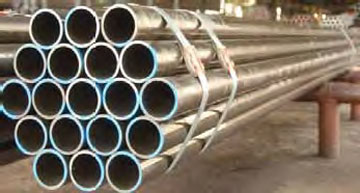
Unlike welded hollow sections, which are made by bending a steel strip and welding it longitudinally, a seamless hollow section is made from solid steel billet by piercing and elongating it. The absence of a weld, and the associated discontinuity in metal properties, ensures complete structural integrity of these hollow sections. Furthermore, since these sections are hot rolled and not cold formed as in the case of welded tubes, the material properties are completely uniform along the cross section. All our tubes conform to European Standards (EN 10210) for hotfinished structural hollow sections.
The UHS Advantage
Total metallurgical integrity
UHS hollow sections do not contain any weld and are hot formed. As a result, these have a fully normalized grain structure and uniform hardness along the cross section. Unlike their welded counterparts, these do not suffer from any weak spots, discontinuities in material properties, or residual stresses along the perimeter of the section.
High strength options
These sections are available in a wide range of steel grades including high strength grades that provide additional flexibility in design. These high strength grades include fine-grain steels and quench and tempered steels.
Wide range of wall thicknesses
Unlike welded structural hollows, which are restricted in wall thickness, UHS hollows are available in a very wide range of wall thicknesses - upto 40mm thick. This makes possible the design of structural elements with uniform external diameters under varying loads. For example, following this principle, the column diameter can be kept constant right through the height of the building.
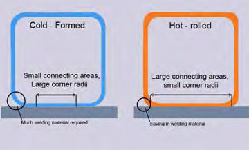
Reduction in welding material and larger connecting areas
Hot rolled hollow sections have smaller corner radii, particularly when higher wall thickness tubes are involved. As a result, the welding material required reduces and the flat contact area increases.
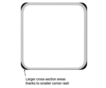
Higher load carrying capability
As a result of the reduced corner radii mentioned above, hot rolled hollow sections have a greater sectional moment and can,therefore, carry higher loads.
Higher buckling loads
Hot rolled seamless sections exhibit better buckling properties than their cold-formed welded counterparts. For this reason, Eurocode 3 norms allow higher buckling loads to be assigned to hot rolled sections.
Effective use of annular space
The empty space within the hollow section can be utilized effectively: UHS columns can be filled with concrete for added strength or with water for fire protection. Alternatively, this space can be used for conveying air-conditioning, electricity or water.
Smaller weld volumes
Weld volumes can be minimized by choosing smaller diameter sections with higher wall thicknesses.
Application
- Office buildings
- Airport terminal
- Machine building
- Sports complexes and stadiums
- Ship building and material handling industry
- Industrial structures and bridge construction
- Agricultural and farming equipments
- Off-shore installations
- Frame structures and body work for locomotives
MANUFACTURING PROCESS
At ISMT, we believe the only way to guarantee quality is to stand responsible for the entire process. For this reason, the steel used for the manufacture of UHS hollow sections is produced in-house through the electric arc furnace route maintaining complete control of the entire production process. The raw material mix is chosen and prepared carefully to ensure the highest standards of cleanliness. All heats are fully killed, ladle refined and vacuum degassed before continuous casting into billets. These ultra-clean round steel billets form the starting point for the manufacture of UHS hollow sections.
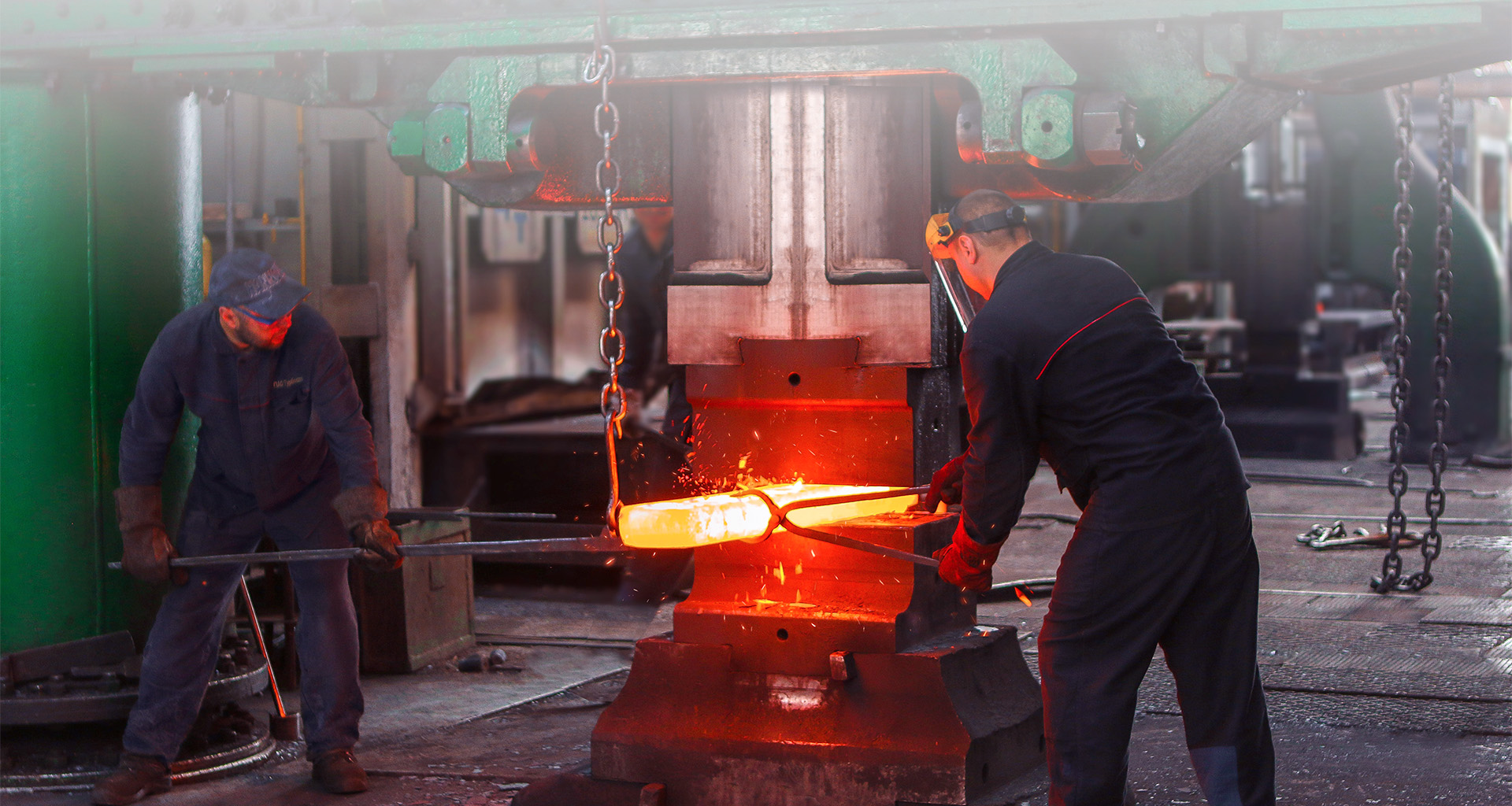
The round steel billets are ?rst heated to between 1,150 and 1,350º C in a rotary hearth furnace. After heating, these billets pass through a cross-roll piercing mill where a carefully positioned piercing point drives a hole through the solid billets to produce elongated rough hollow blooms. These hollow blooms are then rolled over a mandrel, either through a three roll Assel Mill or through a PQF Mill, and eventually through a stretch reducing mill, to produce accurately sized, hot rolled hollow sections.
Stringent process control continues right through the manufacturing and testing process so that we are able to consistently deliver UHS hollow sections with the exact qualities that are required.
Chemical analysis (%)
GRADE | C | Si | Mn | P | S | N |
Specified thickness( mm) |
||||||
40 | ||||||
S235JRH | 0,17 | – | 1,40 | 0,040 | 0,040 | 0,009 |
S275J0H | 0,20 | – | 1,50 | 0,035 | 0,035 | 0,009 |
S275J2H | 0,20 | – | 1,50 | 0,030 | 0,030 | – |
S355J0H | 0,22 | 0,55 | 1,60 | 0,035 | 0,035 | 0,009 |
S355J2H | 0,22 | 0,55 | 1,60 | 0,030 | 0,030 | – |
S355K2H | 0,22 | 0,55 | 1,60 | 0,030 | 0,030 | – |
Carbon Equivalents (cev) %
GRADE | For specified thickness mm | |
16 | 16 40 | |
S235JRH | 0,37 | 0,39 |
S275J0H | 0,41 | 0,43 |
S275J2H | 0,41 | 0,43 |
S355J0H | 0,45 | 0,47 |
S355J2H | 0,45 | 0,47 |
S355K2H | 0,45 | 0,47 |
Mechancial Properties
GRADE | Min. Yield Strength (ReH) Mpa | Tensile Strength Rm) MPa | Elongation % Minimum | Min Impact Strength | ||||
Specified thickness mm/td> | Specified thickness mm | Specified thickness mm | ||||||
Long. | Transv. | T°C | J | |||||
16 | 16 40 | 3 | 3 40 | 40 | 40 | |||
S235JRH | 235 | 225 | 360-510 | 360-510 | 26 | 24 | 20 | 27 |
S275J0H | 275 | 265 | 430-580 | 410-560 | 23 | 21 | 0 | 27 |
S275J2H | 275 | 265 | 430-580 | 410-560 | 23 | 21 | -20 | 27 |
S355J0H | 355 | 345 | 510-680 | 470-630 | 22 | 20 | 0 | 27 |
S355J2H | 355 | 345 | 510-680 | 470-630 | 22 | 20 | -20 | 27 |
S355K2H | 355 | 345 | 510-680 | 470-630 | 22 | 20 | -20 | 40 |
Chemical analysis (%)
GRADE | C | Si | Mn | P | S | Nb | V | Al tot. | Ti | Cr | Ni | Mo | Cu | N |
S275NH | 0.20 | 0.40 | 0.50-1.40 | 0.035 | 0.030 | 0.050 | 0.08 | 0.020 | 0.03 | 0.30 | 0.30 | 0.10 | 0.35 | 0.015 |
S275NLH | 0.20 | 0.40 | 0.50-1.40 | 0.030 | 0.025 | 0.050 | 0.08 | 0.020 | 0.03 | 0.30 | 0.30 | 0.10 | 0.35 | 0.015 |
S355NH | 0.20 | 0.50 | 0.50-1.40 | 0.035 | 0.030 | 0.050 | 0.12 | 0.020 | 0.03 | 0.30 | 0.50 | 0.10 | 0.35 | 0.020 |
S355NLH | 0.18 | 0.50 | 0.50-1.40 | 0.030 | 0.025 | 0.050 | 0.12 | 0.020 | 0.03 | 0.30 | 0.50 | 0.10 | 0.35 | 0.020 |
S420NH | 0.22 | 0.60 | 1.00-1.70 | 0.035 | 0.030 | 0.050 | 0.20 | 0.020 | 0.03 | 0.30 | 0.80 | 0.10 | 0.70 | 0.025 |
S420NLH | 0.22 | 0.60 | 1.00-1.70 | 0.030 | 0.025 | 0.050 | 0.20 | 0.020 | 0.03 | 0.30 | 0.80 | 0.10 | 0.70 | 0.025 |
S460NH | 0.22 | 0.60 | 1.00-1.70 | 0.035 | 0.030 | 0.050 | 0.20 | 0.020 | 0.03 | 0.30 | 0.80 | 0.10 | 0.70 | 0.025 |
S460NLH | 0.22 | 0.60 | 1.00-1.70 | 0.030 | 0.025 | 0.050 | 0.20 | 0.020 | 0.03 | 0.30 | 0.80 | 0.10 | 0.70 | 0.025 |
Carbon Equivalents (CEV) %
GRADE | Maximum Carbon Equivalent (CEV) | |
For specified thickness mm | ||
16 | 16 40 | |
S275NH | 0.40 | 0.40 |
S275NLH | 0.40 | 0.40 |
S355NH | 0.43 | 0.43 |
S355NLH | 0.43 | 0.45 |
S420NH | 0.50 | 0.52 |
S420NLH | 0.50 | 0.52 |
S460NH | 0.53 | 0.55 |
S460NLH | 0.53 | 0.55 |
Mechanical properties
GRADE | Min. Yield Strength (ReH) MPa |
Tensile Strength (Rm) MPa |
Elongation % Minimum | Minimum Impact Strength* | |||
Specified thickness mm | Specified thickness mm | Specified thickness mm | T°C/ | J | |||
= 16 | 16 = 40 | Long. | Transv. | ||||
S275NH | 275 | 265 | 370-510 | 24 | 22 | -20 | 40 |
S275NLH | 275 | 265 | 370-510 | 24 | 22 | -50 | 27 |
S355NH | 355 | 345 | 470-630 | 22 | 20 | -20 | 40 |
S355NLH | 355 | 345 | 470-630 | 22 | 20 | -50 | 27 |
S420NH | 420 | 400 | 520-680 | 19 | 17 | -20 | 40 |
S420NLH | 420 | 400 | 520-680 | 19 | 17 | -50 | 27 |
S460NH | 460 | 440 | 540-720 | 17 | 15 | -20 | 40 |
S460NLH | 460 | 440 | 540-720 | 17 | 15 | -50 | 27 |
application in the construction of bridges, cranes, off-shore structures, buildings, ships and other structures where reduction of dead weight without any loss of load bearing capacity is critical.
Typical characteristics of these tubes are high yield strengths and good toughness with the guarantee of chemistry that is suitable for welding. Tubes are produced as per following chemical analysis that guarantee the required mechanical properties which generally conform to EN 10297 specifi cation.
CHEMICAL ANALYSIS (%)
C | Mn | vc | P | S | Ni | V | Cr | Mo |
0.20 | 1.70 | 0.60 | 0.025 | 0.015 | 1.20 | 0.12 | 0.50 | 0.50 |
Mechanical Properties
GRADE | TENSILE PROPERTIES | IMPACT TEST* | |||||||
Rp02 (MPa) min | Rm (MPa) min | A % | Charpy KV long. | Charpy KV Trasv. | |||||
long. min | (J min) | ||||||||
Wall thickness mm | Temperature | ||||||||
20 | 20 40 | 20 | 20 40 | -20 °C | -50 °C | -20 °C | -50 °C | ||
HS620 | 620 | ||||||||
HS690 | 690 | 650 | 770-960 | 720-930 | 16 | 55 | - | 27 | - |
HS770 | 770 | 700 | 820-1000 | 750-960 | 15 | 50 | - | 27 | - |
HS790 | 790 |
circular hollow - sections
Outside | Wall thickness | ||||||||||||||||||
Diameter | Mm | ||||||||||||||||||
mm | 8.0 | 2.6 | 2.9 | 3.2 | 3.6 | 4.0 | 4.5 | 5.0 | 5.6 | 6.3 | 7.1 | 8.0 | 8.8 | 10.0 | 12.5 | 16.0 | 20.0 | 30.0 | 40.0 |
21.3 | 1.08 | 1.20 | 1.32 | 1.43 | 1.57 | 1.71 | 1.86 | 2.01 | |||||||||||
33.7 | 2.20 | 2.41 | 2.67 | 2.93 | 3.24 | 3.54 | 3.88 | 4.26 | 4.66 | 5.07 | |||||||||
42.4 | 2.82 | 3.09 | 3.44 | 3.79 | 4.21 | 4.61 | 5.08 | 5.61 | 6.18 | 6.79 | 7.29 | 7.99 | |||||||
48.3 | 3.25 | 3.56 | 3.97 | 4.37 | 4.86 | 5.34 | 5.90 | 6.53 | 7.21 | 7.95 | 8.75 | 9.45 | |||||||
60.3 | 4.51 | 5.03 | 5.55 | 6.19 | 6.82 | 7.55 | 8.39 | 9.32 | 10.3 | 11.2 | 12.4 | 14.7 | |||||||
76.1 | 5.75 | 6.44 | 7.11 | 7.95 | 8.77 | 9.74 | 10.8 | 12.1 | 13.4 | 14.6 | 16.3 | 19.6 | 23.7 | 27.7 | |||||
88.9 | 7.51 | 8.38 | 9.37 | 10.3 | 11.5 | 12.8 | 14.3 | 16.0 | 17.4 | 19.5 | 23.6 | 28.8 | 34.0 | ||||||
101.6 | 9.63 | 10.8 | 11.9 | 13.3 | 14.8 | 16.5 | 18.5 | 20.1 | 22.6 | 27.5 | 33.8 | 40.2 | |||||||
114.3 | 12.2 | 13.5 | 15.0 | 16.8 | 18.8 | 21.0 | 22.9 | 25.7 | 31.4 | 38.8 | 46.5 | 62.4 | |||||||
139.7 | 15.0 | 16.6 | 18.5 | 20.7 | 23.2 | 26.0 | 28.4 | 32.0 | 39.2 | 48.8 | 59.0 | 81.2 | |||||||
168.3 | 20.1 | 22.5 | 25.2 | 28.2 | 31.6 | 34.6 | 39.0 | 48.0 | 60.1 | 73.1 | 102 | 127 | |||||||
177.8 | 26.6 | 29.9 | 33.5 | 36.7 | 41.4 | 51.0 | 63.8 | 77.8 | 109 | 136 | |||||||||
193.7 | 29.1 | 32.7 | 36.6 | 40.1 | 45.3 | 55.9 | 70.1 | 85.7 | 121 | 152 | |||||||||
219.1 | 33.1 | 37.1 | 41.6 | 45.6 | 51.6 | 63.7 | 80.1 | 98.2 | 140 | 177 | |||||||||
244.5 | 46.7 | 51.2 | 57.8 | 71.5 | 90.2 | 111 | 159 | 202 | |||||||||||
273.0 | 64.9 | 80.3 | 101 | 125 | 180 | 230 | |||||||||||||
Other outside diameter and wall thickness on request |
circular hollow - sections
Size | Wall thickness | |||||||||||||||||
mm | Mm | |||||||||||||||||
40x40 | 2.9 | 3.2 | 3.6 | 4.0 | 4.5 | 5.0 | 5.6 | 6.3 | 7.1 | 8.0 | 8.8 | 10.0 | 11.0 | 12.5 | 14.2 | 16.0 | 17.5 | 20.0 |
50x50 | 3.31 | 3.61 | 4.01 | 4.39 | 4.85 | 5.28 | 5.78 | 6.33 | 6.91 | |||||||||
60x60 | 4.22 | 4.62 | 5.14 | 5.64 | 6.26 | 6.85 | 7.54 | 8.31 | 9.14 | 10.0 | ||||||||
70x70 | 5.13 | 5.62 | 6.27 | 6.9 | 7.67 | 8.42 | 7.30 | 10.3 | 11.4 | 12.5 | 13.5 | 14.9 | 15.9 | 17.3 | ||||
80x80 | 6.63 | 7.40 | 8.15 | 9.08 | 9.99 | 11.1 | 12.3 | 13.6 | 15.0 | 16.3 | 18.0 | 19.4 | 21.3 | |||||
80x80 | 8.53 | 9.41 | 10.5 | 11.6 | 12.8 | 14.2 | 15.8 | 17.5 | 19.0 | 21.1 | 22.8 | 25.2 | ||||||
90x90 | 9.66 | 10.7 | 11.9 | 13.1 | 14.6 | 16.2 | 18.1 | 20.1 | 21.8 | 24.3 | 26.3 | 29.1 | ||||||
100x100 | 11.9 | 13.3 | 14.7 | 16.3 | 18.2 | 20.3 | 22.6 | 24.5 | 27.4 | 29.7 | 33.0 | 33.6 | ||||||
110x110 | 13.2 | 14.7 | 16.3 | 18.1 | 20.2 | 22.5 | 25.1 | 27.3 | 30.6 | 33.2 | 37.0 | 41.0 | ||||||
120x120 | 16.1 | 17.8 | 19.9 | 22.2 | 24.7 | 27.6 | 30.1 | 33.7 | 36.6 | 40.9 | 45.5 | 50.1 | ||||||
140x140 | 21.0 | 23.4 | 26.1 | 29.2 | 32.6 | 35.6 | 40.0 | 43.5 | 48.7 | 54.4 | 60.1 | 64.7 | ||||||
150x150 | 28.1 | 31.4 | 35.1 | 38.4 | 43.1 | 47.0 | 52.7 | 58.9 | 65.2 | 70.2 | ||||||||
Other outside diameter and wall thickness on request | [Weight in kg/m] |
Tolerances
Tolerances will be as per EN 10297 specifications.
Permissible deviation in external dimensions D, B and H ….±1% With a minimum of ±0.5mm.
Tolerance on wall thickness T …. -10% for Seamless section, local deviation of -12.5% are permissible.
Permissible out-of-roundness 0 ………….2% out-of-roundness is calculated using the following equation:
0(%) = | Dmax – DMin | X 100 |
D |
In the case of square USH sections, the wall thickness in the straight edge area must be checked the upper layer of the wall thickness is determined by the maximum weight.
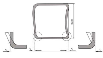
Maximum Permissible deviation of squareness of sides ...± 1°
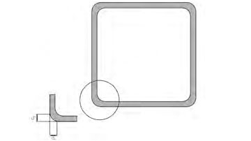
External Cornor Profile
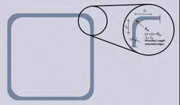
C1 & C2 = max. 3T (wall thickness) the distance between the intersection of the fl at side and the corner arc and the intersection of the projections of the fl at sides to the corner C1 and C2 shall be measured
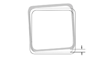
The maximum permissible twist V is calculated using the following formula: V =
2mm + 0.5mm/m
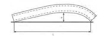
Permissible out-of-straightness = 0.2% related to the total section length, i.e.
2mm/m
Maximum mass tolerance per section = ±6%, ±8%.
Type of length | Available length(mm) | Permissible deviation | Ordering information re length |
Mill length | 6000 – 16,000 | 1) | none |
Fixed length | 2,000 | ±500 | Required fixed length in mm |
2,000 | –0 +10 | Required fixed length in mm | |
6,000 | |||
6,000 | –0 +15 |
All the steel grades indicated in this brochure have been specially developed so that they have a low carbon equivalent and are easily weldable using traditional welding procedures (provided generally accepted technical rules are followed). For very thick sections, precautions should be taken to avoid cold cracking. In such cases, pre-heating prior to welding is advisable.
Lengths
Standard lengths supplied by ISMT are from 5 to 10 mtrs long. Tubes in exact length based on specific request can also be supplied.
End Preparation
Tubes with square cut ends or bevelled ends can be supplied.
Packaging And Marking
Each tube is oiled internally and externally and then packed into round/ hexagon bundles. This ensures that tubes are protected from corrosion and that tubes retain their straightness during transport. Our standard marking (painting) includes:
- Name and trade mark
- Dimensions
- Steel designation e.g. EN 10210 - S355J24
- Batch number
Inspection And Testing
Tubes are subjected to following tests (which conform to EN 10210)
- Cast analysis
- Tensile test
- Impact test
- Visual and dimensional check
ISMT manufactures carbon/alloy steel and seamless tubes for:
- Energy and Power Generation
- Automotive Components
- Hydraulic and Pneumatic Pressure Lines
- Hydraulic Cylinders
- Gas Cylinders
- Mining and Construction
- Bearings
- General Engineering Applications
- Oil and Petroleum Applications
Product details are available on request.